language:
English
GRANIT-ONIX program-controlled technological complex is designed for information support of oil and gas wells testing and operation control. The complex comprises: a set of downhole modules, controlling and recording hardware, software for data processing and interpretation.GRANIT Downhole Equipment
1. GRANIT Downhole Equipment 1.1 Conception:
- the equipment consists of a set of modules;
- each module is an independent multiparameter or single parameter tool connected to a transit central conductor;
- several modules of a single string when switched are automatically networked (multichannel information network);
- combination of modules and each module in a string can operate independently in the mode of continuous generation of coded signals as well as under the action of control signals from a logging unit;
- modules can operate with a wide range of supply voltage (25 ... 100 V at cable bottom), under up to 100 MPa pressure and up 1500C.
1.2 Basic set of equipment
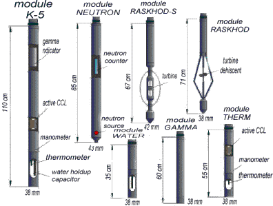
A basic set of equipment comprises the following modules (diameter 38 mm):
- K-5 (thermometer, manometer, active CCL, water holdup capacitor, gamma indicator) 113 cm long;
- PRITOK (thermoanemometer, induction resistometer, three-channel indicator of acoustic noise) 61 cm long
- RASKHOD (turbine flowmeter) 80 cm long;
- NEUTRON (neutron logging), diameter 42 mm, 70 cm long.
1.3 Main metrological parameters
- Temperature: accuracy 0.5, resolution 0.05 (% of range).
- Preassure: accuracy 0.5, resolution 0.05 (% of range).
1.4 Power supply
Modules are powered with voltage arriving via central cable conductor from the unit. Positive polarity, voltage operating range - 30...40 V. In 40-100 V range modules keep normal operation, but thermoanemometer is switched off. Voltage control at the cable bottom is performed via service channels of a telemetry system. The average current consumption of each module is 30 mA. With thermoanemometer switched on current increases of 80 mA. Thus supply current for a combination of 5 modules is not more than 200 mA.
1.5 Interface
Data are transmitted via cable conductor as a sequence of negative pulses, applied to supply voltage. All time intervals in a transmitted code are multiples of T=64 µs time interval. T stands for a pulse duration at the cable bottom. Time interval between leading edges is 2T for a zero bit and 3T for a unit bit. Specific # of channels are allotted to each module according to the module description stored in the system. When several modules are connected to the cable they automatically form a cyclic queue.
1.6 Metrology
The individual set of metrological parameters for each module is kept in the subsystem of equipment maintenance. This set is used to convert numeric codes of measuring channels into named physical units of measurements, for instance: degrees, atmospheres or into arbitrary unit of 0...100 scale. Metrological set is automatically selected when serial #-s of modules in a string are specified. Serial numbers are stored in each module processor memory and can be tested after switching. Linear scale is used for most sensors. In some cases, say for pressure, correction factors derived from data of other channels are used for calculation of a named parameter. Calibration is done in a semi-automatic mode with a special program block being used. Calibration concept resides in creating corresponding physical conditions for some specific sensor and inputting the readings of a reference measuring device. After that module is calibrated against a reference standard.
2. Subsystem of Recording
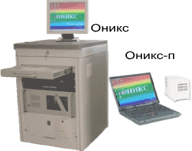
ONIX measuring subsystem and Interface package provide for :
In terms of equipment servicing subsystem provides for:
- downhole tools power supply (d.c. up to 100V, current up to 500 mA, parameters can be program-set;
- automatic setting of power parameters of GRANIT equipment downhole modules;
- generation of control signals in the form of voltage pulses and numeric serial code, sent to a logging cable;
- generation of control signals in the form of voltage pulses and numeric serial code, sent to a logging cable;
- 4 channels receipt, digitizing and recording of measuring panels output voltages;
- receipt of depth sensor signals (optical or synchro pickup) and cable magnetic marks
While production logging subsystem provides for:
- support of data base of hardware under use with the description of all required parameters (including metrological) of downhole modules;
- setting and control of power parameters and information pulses of downhole tools;
- calibration of downhole modules measured parameters and storage of individual metrological description of each module;
- viewing and analysis of signal form with computer oscillograph.
Graphics control of measured parameters curves provides for:
- control, setting and correction of downhole tools current depth;
- control of downhole tools runninig-in or pulling speed;
- control of logging cable magnetic marks and automatic correction of depth by marks;
- control of physical parameters with the use of metrological processing in digital and graphics forms;
- record measured parameters on computer disk with tying to depth and time including recording points of each parameter and conditions of measurement on the whole:
- input of conditions for the program to generate signals.
Measuring system operates in a background mode that allows for processing of previous measurements.
- on-line curves displaying or printing in any suitable format and scale;
- graphs scanning by depth or by time;
- display of well design elements on a graph;
- while recording its possible to scroll and page a graphic display from the start of recording..
3. Subsystem of Data Processing
Software to process ONIX data is developed for on-line processing of complex measurement of great number of parameters (pressure, temperature, inflow-composition methods, etc.), including data of hydrodynamic survey.
Processing system can be subdivided into 2 levels:
The first level provides for logs processing by a sequence of methods, microprograms file recorded.
The second level is formed by a set of macroprograms with complex algorithms of processingMacroprograms allow for complete automatization of many processing stages, up to reports generation with preliminary interpretation conclusions. Processing can be conducted either in lab or on-site in semi-automatic mode to acquire preliminary results of studies and pass them to a customer.
170034, Russia, Tver street Tereschenko 5/25
Telephone: (4822)-32-43-80
Fax: (4822)-36-73-53

